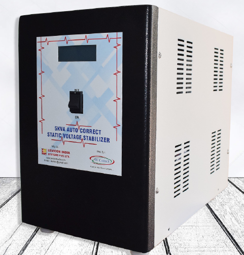
Static Voltage Stabiliser
Auto Correct
Static Voltage Stabilizer Using Igbt And Dsp
Introduction
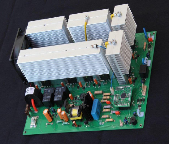
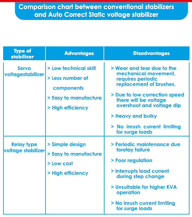
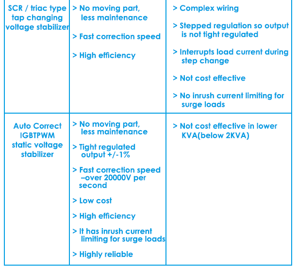
Levicons Static Voltage Stabilizer is an IGBT based PWM type buck- boost voltage stabilizer which has tight regulation and fast correction speed which is impossible to obtain using conventional methods such as servo voltage stabilizers, SCR / triac type stabilizer,relay type stabilizer etc. This is an SMPS type voltage stabilizer for mains voltage (AC input and AC output). This is a new switching topology where PWM is made directly in AC-to-AC switching, without any harmonic distortion. In this topology there is no need to convert the AC input to DC and again convert it back to regulated AC output. This simplifies the design, reduces the component count and improves the efficiency and reliability. The power stage is an IGBT chopper control. The chopping frequency is around 20KHz which ensures absolutely silent operation and pure sine wave output (no waveform distortion).
The control section is based on dsPIC controller which ensures quick correction of output which is not possible in conventional relay type stabilizer or servo controlled stabilizers. The circuit is having LCD for display which will show all parameters like: input voltage, output voltage, connected load, your company name (We will program your company name in the dsPIC at the time of technology transfer) etc.
Since the circuit is fully solid state (no mechanical or moving parts),there will not be any wear and tear like the brush tear in servo stabilizer or relay degrading in relay based stabilizer. This is specially useful in places where we need very fast correction speed, constant output voltage, overload current limiting and short circuit protection, soft start, high voltage cut-off and low voltage cut-off, automatic bypass, no wear and tear, long life and maintenance free which is impossible with other conventional relay type or servo control stabilizers.
How It Works
Let me explain what it is in brief – In this IGBT based PWM type static voltage stabilizer only the difference voltage is switched through IGBT and will be added or subtracted from the mains. This is done electronically without any step changing in voltage which occurs when the system regulates. This is achieved by a feedback control system using digital signal processor (DSP). The output voltage is sensed by the DSP and corrections are made by varying the duty cycle of the PWM.This stabilizer boosts up the voltage if it is low and bucks the voltage if it is high.
For example – If the AC input is 200V and the AC output is set for 220V, only 20V will be regulated through the IGBT and will be added to the original mains source which is 200V. If the AC input is 195V, then 25V will be added…. So the power and current in the IGBT will be very less (less than 1/5th of the total load if the range is 180V to 260V).
For example – In a 5KVA (5000VA) stabilizer if AC input is 195V, then 25V will go through the PWM stage.
So, the output current is 5000 / 220 = 22.7A.
So, the difference power is 22.7A * 25V = 568VA
Therefore, the current through the IGBT = 568VA / 195V = 2.9A only.
Similarly, if the AC input is 240V, then 20V will be subtracted.
This means, we can use discrete IGBTs and make the circuit very compact and very high efficient and cost effective. The efficiency in worst case will also be above 97%. This stabilizer is ideal for mobile towers, CNC machines, medical equipment, textile industries, power plants and any industrial product that needs tight regulation and fast correction. We can also use this for Air Conditioners, refrigerators, motor, pump etc.
The transformer size will be only 1 /5′ of the output power. For 10KVA stabilizer transformer size will be that of 2KVA.
Highlights of Autocorrect
- Instantaneous correction speed – over 20000V per second
- Discrete IGBT up to 30KVA single phase and 90KVA three phase
- Single PCB for control stage, IGBT driver section and power stage.
- Lower BOM and easy to assemble.
- Single contactor for three phase system.
- Single LCD for three phases.
- All protections included – low voltage, high voltage, overload and short circuit.
Waveforms
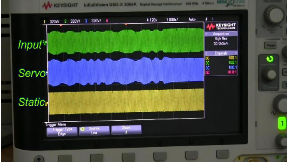
The unique feature of this stabilizer is its correction speed which is very fast. If there is any change in the input voltage, it will be corrected in the very next cycle.
Channel 1 (yellow) is the input waveform.
Channel 2 (blue) is the output waveform.
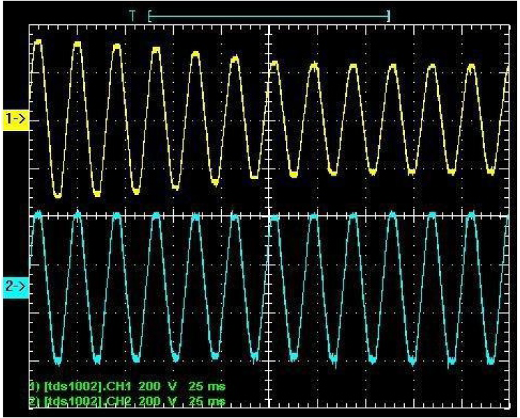
As we can see in the above waveform, input voltage (channel 1 – yellow) is dragged down from high voltage to low voltage within 0.2sec, but the output voltage (channel 2 – blue) remains steady.
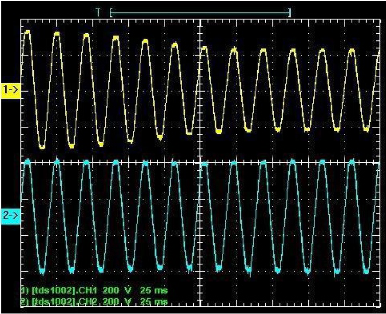
Input voltage (channel 1 – yellow) is dragged up from low voltageto high voltage within 0.2sec, but the output voltage (channel 2 – blue) remains steady.
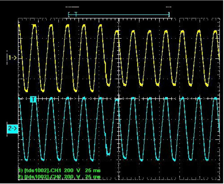
The input voltage stepped down from high voltage to low voltage in no time, and the output voltage (channel 2 – blue) corrected immediately in the next cycle.
Features
- Direct AC-AC conversion without rectifying to DC improves the efficiency, reliability and reduces the components.
- Rapid cycle by cycle correction of output. It can correct sudden fluctuation in the line voltage. For example using a welding machine in the same line will cause sudden fluctuation in the line voltage which can not be corrected with conventional relay type and servo controlled voltage stabilizers, where Static Voltage Stabilizer can correct it.
- Output regulation of +/- 1% which is impossible in conventional stabilizer.
- No distortion in output waveform.
- Overload cutoff and short circuit cut off
- Over voltage and under voltage cutoff.
- Automatic bypass incase of failure.
- LCD display for displaying all parameters and your company name.
- Small transformer size (1 /5th of the capacity)
- Compact size and light weight
- 20KHz PWM control
- IGBT power stage. Highly reliable.
- Fully solid state. No moving part, hence more life and no maintenance.
- Silent operation.
Reliability
- Over load and short circuit protection: It has overload/ short circuit current limiting and cut-off, the control part of the static stabilizer will sense the output current and if the load is more than the rated VA, for example: In a 3KVA stabilizer, if you accidentally connect a load of 10KVA, it will limit the output current to the maximum output current at full load of the stabilizer.
- High input voltage cut off : The high input voltage cut-off is set for 270V ( it can be set for some other voltage also ) up to 270V input, the output will be constant 220V. Because of this high voltage cut-off, the stabilizer itself will be protected from high voltage and the connected load is also safe.
- Low voltage cut off : The low voltage cut off can be set at any value. For example – in a 180V to 260V model, the low voltage cut-off can be set at 180V or 170V or lower. Because of this low voltage cut off, the stabilizer is protected from low voltage malfunctioning.
- Wear and tear : There is no wear and tear like the conventional stabilizer, as this stabilizer is fully solid state andthere is no moving part. Because of this, there is no need of replacement of components even after certain period due to ageing. This eventually increases the reliability of the static stabilizer.
All the above protections and safety measures are not incorporated in the conventional stabilizers and that is what makes our differential power mode static stabilizer very reliable and unique.
Efficiency
It is because of the topology, this stabilizer has very high efficiency. In this topology, only the difference power is switched through the IGBTs as explained under the Working, 1/5th of the total power is only switched through the IGBT even at the worst case. Otherwise it is less than 1 15th of the total power in normal case. So for a 10KVA stabilizer, in the worst case 2KVA is switched through the IGBTs. The current through the IGBT will be 2000VA ± 180V = 11A.
• Conduction loss
The lnfineon IGBT IKW75N60T has a voltage drop (Vce(sat)) of 1.8V in
worst case. So the conduction loss = 1.8V x 11A = 20VA. This will come
in two IGBTs so the total conduction loss will be 40VA.
• Diode loss
The maximum diode forward voltage drop of the IGBT is 1.7V. So, the conduction loss in the diode is 1.7V x 11A = 19VA. This will come in two IGBTs so the total diode conduction loss will be 38VA.
• Switching loss
The optimum switching frequency selected is 18KHz so we can minimize the switching loss and there will not be any audible noise. The switching loss per IGBT at full load (11A) is measured to be 30VA. This will come in two IGBTs so the total switching loss will be 60VA.
• Transformer loss
The cost effective buck – boost transformer as per our winding data will have an efficiency above 95% at full load. So the loss in
the transformer is 5%. Loss in the transformer = 2000VA x 5% = 100VA.
The overall loss in the system = conduction loss + diode loss + switching loss+ transformer loss
Which is, System loss = 40VA + 38VA + 60VA + 100VA = 238VA
Therefore, for an output of 10KVA (10,000VA), the input will be
10000VA + 238VA = 10238VA
So, the system efficiency = output power x 100 =10000 x 100 = 97.68% Input power 10238
The overall system efficiency = 97.68%
We can easily achieve the buck-boost transformer efficiency of 98% using CRGO core, then the transformer loss will be 40VA at full load. So the overall system efficiency will be 98.25%.
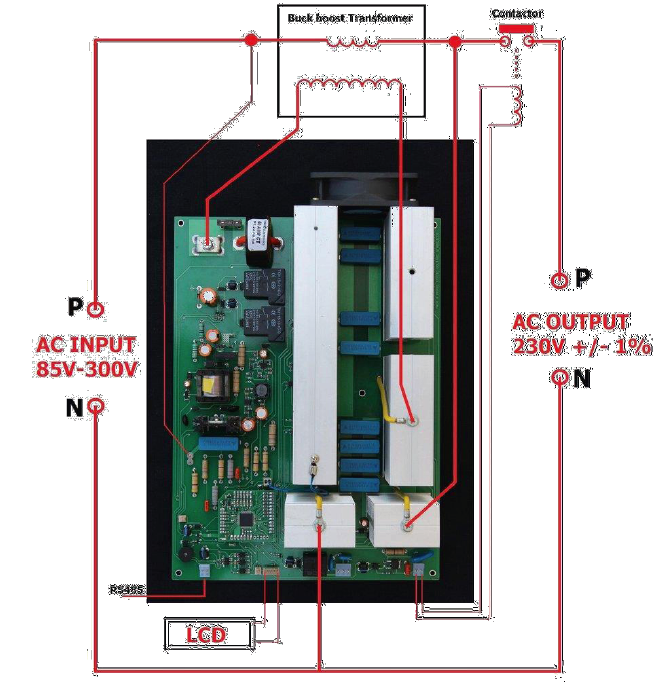
Varying input given to servo stabilizer and Auto Correct
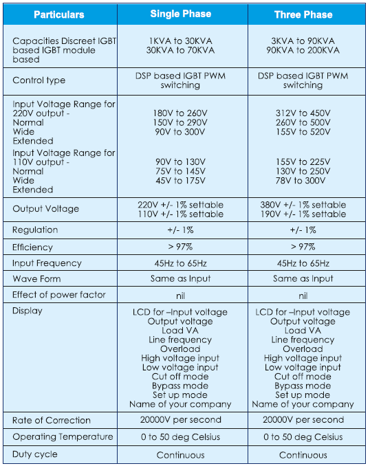
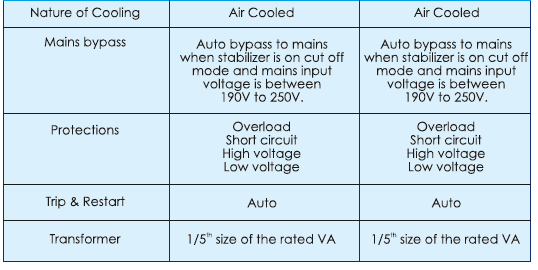
Specifications